The LDR Sensor also know as the Photo-resistor is basically a simple sensor that its resistance value changes with light. (resistance will lower with more light.)
The LDR isn’t very precise, so you can not get a LUX reading but it is good enough to tell the difference between light and shadow.
It can be used to make:
- Automatic light dimmer
- Light sensitive switch

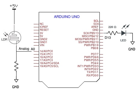
LDR Sensor with Arduino
Parts List
- Arduino
- LDR (also known as a photocell)
- LED with 220 to 330 ohm resistor
- 1K to 10K resistor (used with the LDR to setup a voltage divider)
Connections
The LDR is a special type of resistor which allows higher voltages to pass through it.
It means with a high intensity of light a low voltage passes.
The circuit based on a photo resistor that uses a resistor divider (4.7K to 10K) to allow the high impedance analog input to measure the voltage.
To get a voltage proportional to the photoresistor value, a resistor divider is necessary.
For demonstration we use an additional LED to digital pin 13 in series with the 220 ohm resistor.
Following formula is used to calculate the voltage at A0 pin (Vout):
Vout=Vin*(R2/(R1+R2))
The voltage input (Vin) referenced to 5V expressed as a 10 bit value.
In other words 5V gets split up into 1024 levels, that is 5/1024 = 0.0048828125 volts per unit returned back.
ADC (analog-to-digital converter) of microcontroller converts and maps the analog value of the LDR from 0-5 volt to a value in 0-1023 range (digital 0-255).
/*
 Reading an analog sensor on analog pin 0 and
 turning on and off a light emitting diode(LED Digital 13).
 http://www.arduino.cc/en/Tutorial/AnalogInput
*/
int sensorPin = A0;    // select the input pin for the potentiometer and 10K pulldown
int ledPin = 13;       // select the pin for the LED

void setup() {
  Serial.begin(9600);     // serial connection
  // declare the ledPin as an OUTPUT:
  pinMode(ledPin, OUTPUT);
}

void loop() {
  // read the value from the sensor and converts to 0 to 1023 range by using ADC
  sensorValue = analogRead(sensorPin);
  digitalWrite(ledPin, HIGH);   // turn the ledPin on
  delay(1000);                  // waits for a second
  digitalWrite(ledPin, LOW);    // turn the ledPin off
  delay(1000);
  // map it to the range of the analog out
  int outputValue = map(sensorValue, 0, 1023, 0, 255);
  analogWrite(ledPin, outputValue); // change the analog out value
  // print the results to the Serial Monitor
  Serial.print("sensor = "); Serial.print(sensorValue);
  Serial.print("\t output = "); Serial.println(outputValue);
 }
Leave a Reply