Solar Monitoring System
ESP-12 based Solar Panel Monitoring System
This system helps you to remotely monitor the power of your solar panels, batteries and the DC load with a smartphone from anywhere.
It’s based on the Nodemcu ESP-12 WiFi module and Blynk application.
The battery and solar voltage with the temperature will be displayed. It’s also possible by using buttons on installed app to decide witch batteries should be charged.
This tutorial try to shows step-by-step how to make it.
- The solar panels output up to 35V with direct sun.
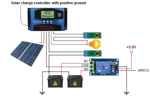
- The solar panels charger is positive ground controller. (And this provide me a lot problems with negative grounded ESP.)
- Two car batteries.
Hardware Requirements
- ESP-12 WiFi module
- 2 x VOLTAGE SENSOR (INA219) for Batteries (from 0 to 26 V)
- VOLTAGE SENSOR (INA229) for Solar (not more needed, replaced with voltage divider)
- 2 x ACS712 Current sensing Module in 30A (Available in 5A, 20A and 30A)
- 4 x resistors used as voltage divider
- 2 x 4 Channels ADS1115 16 Bit ADC Board (I2C, address 0x48)
- Temperature Sensor Devices:
- LM35 Integrated Circuit (range of 0-100°C) (Not used in version 1)
- DHT11 Temperature/Humidity sensor (Used to measure the inside temperature around batteries.)
- BMP280 Barometric Pressure + Temperature Sensor (Not used in version 1)
- 1 x DS18b20 Temperature sensors (Used to measure the outside temperature.)
- Power supply 3.3V for ESP module and 5V for the others such as 2xACS712 modules
 Two Channel Relays
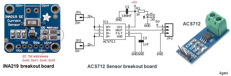
The voltage of batteries can be messure by INA229 module. (but I replaced the sensors with voltage divider)
The maximum input voltage for INA219 is 26 V and for INA229 is limited to 36 V and the current measurement is limited to ±3.2A with a resolution of ±0.8mA.
The devices use a 3 to 5.5-V supply and can be assigned to 4 different I2C addresses (0x40, 0x41, 0x42, 0x43).
The Adafruit_INA219 library provides an approach and calibrations by setting up the INA219.
| Solder A1 | Solder A0 | INA219 Address |
|---|---|---|
| – | – | 0x40 |
| – | Connected to VCC | 0x41 |
| Connected to VCC | – | 0x44 |
| Connected to VCC | Connected to VCC | 0x45 |
#include "Wire.h";
#include "Adafruit_INA219.h";

Adafruit_INA219 ina219_B1;
Adafruit_INA219 ina219_B2(0x41);

void setup(void) {
   ina219_B1.begin(); // Initialize first board (default address 0x40)
   ina219_B2.begin(); // Initialize second board with the address 0x41
}
At this moment I’m using voltage dividers to measure the voltages in my project.
To measure the currents I’m using two ACS712 modules (hall effect device) .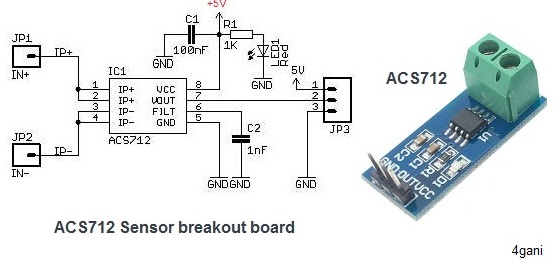
One sensor measures the current of battery charger and the other one the current of the load.
The ACS712 has to be fed with 5V and the analog outputs voltage is proportional to measured current on the sensing terminals.
The sensor is bi-directional so it will give 2.5V output even if not current is flowing through it. (below my calculation to get current values).
The module gives a sensitivity of 0.1V/A in 20A and available in 5A, 20A and 30A.
The ADS1115 is a 16-bit analog-to-digital converter and I’m using to read the voltage from Hall sensor.
The ADS1115 can be addressed with one of four I2C addresses. (0x48, 0x49, 0x4a, 0x4b).
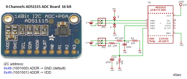
Voltage Supply (Vdd): 2 ~ 5V
Measurement range: -300mV to Vdd+300mV
Data rate: 8 ~ 860 SPS
Active current: ~150uA (200uA max)
I’m using ADS1115 in two channel and in GAIN_ONE mode.
In GAIN_ONE mode the voltage can be measured up to maximum 4V and provides a resolution of 0.125mV per bit. (4.096 volts / 32767 bits )
I calculated the ADC in gain_one program mode together with ACS as followed:
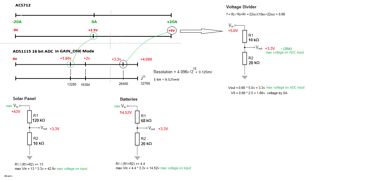
We can not connect up to a 3.3V voltage an ADC input!
So we using a voltage divider to bring the voltage between 0V and 3.3V.
R1 = 10k, R2 = 20kR2/(R1 + R2) => 0.66 => 1/0.66=1.51ADC(MaxVin) = 0.66 * 5V = 3.3V
The ACS sensor have zero current by 2.5V. This corresponds to the voltage 1.65V at ADC and also 13200 bits.
So I can calculate the current as followed:multiplier = 0.000125F; /* ADS1115 @ +/- 4.096V gain_1 (16-bit results) */aMultiplier = multiplier * ( 1/0.66)
Now we read the input AIN2 digital value of 16 bits ADC adc = ads.readADC_SingleEnded(2); current = (adc - 13200 ) * aMultiplier ) / (2.5/20)); // in Ampere
#include "Wire.h";
#include "Adafruit_ADS1015.h";

Adafruit_ADS1115 ads48(0x48); // use for the 16-bit
Adafruit_ADS1115 ads49(0x49); // use for the 16-bit

void setup(void) {
   // ads.setGain(GAIN_ONE);  // 1x gain +/- 4.096V 1 bit = 2mV 0.125mV
   ads48.begin();
   ads49.begin();
   ...
}
...
int16_t adc = ads48.readADC_SingleEnded(2);
float volt = (adc * 0.125) / 1000 * 4.4;
Serial.print("Battery Voltage:");
Serial.print(volt); Serial.println(" V");
High temperature can damaged the batteries.
The purpose to use DHT11 or DS18B20 temperature sensors is to enable us to compare the battery temperature with the environment temperature.
I’m using one sensor for environment and one for battery.
The mobile app will display the temperatures and humidity.
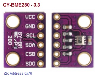
BME280 Barometric Pressure + Temperature Sensor
BME280 is the next-generation digital temperature, humidity and pressure sensor manufactured by Bosch.
The operating voltage of the BME280 module is from 3.3V to 5V
The default I2C address of the BME280 module is 0x76 and can be changed to 0x77 with the solder jumper on the chip.
#include "Wire.h";
#include "Adafruit_Sensor.h";
#include "SparkFunBME280.h"
#include "math.h"

BME280 bme;

void setup(void) {
  Serial.begin(115200);
  Serial.println(F("Initialize BME280 with 0x76."));
  bme.settings.commInterface = I2C_MODE;
  bme.settings.I2CAddress = 0x76;
  bme.settings.runMode = 3; //Normal mode
  bme.settings.tStandby = 0; // 0, 0.5ms
  bme.settings.filter = 0; //0, filter off
  bme.settings.tempOverSample = 1;
  bme.settings.pressOverSample = 1;
  bme.settings.humidOverSample = 1;
  Serial.println(bme.begin(), HEX);
  ...
}

float T = bme.readTempC();
Serial.print("Temperatur: "); Serial.print(T,1); Serial.println(" °C");
float pH = bme.readFloatPressure()/100.0;
Serial.print("Atmospheric pressure at current location: "); Serial.print(pH, 1); Serial.println(" hPa");
float H = bme.readFloatAltitudeMeters();
Serial.print("Altitude: "); Serial.print(H,1); Serial.println("m");
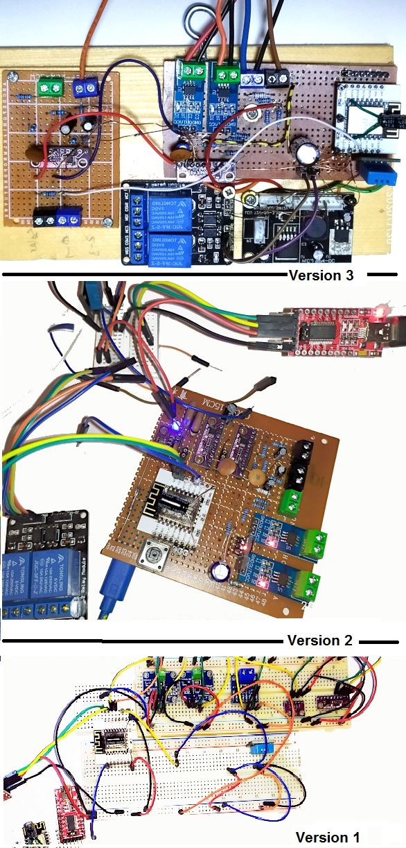
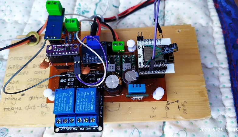
The whole system (The draft version have problems with them positive ground charger)
– It’s also nice to have a light sensor to read the daylight intensity. Schematic and Wiring Diagram: (next generation) My controller is positive-grounded. It means the positive of solar, battery and load are hard-wired together inside the unit which makes my life hard. I removed INA219 and INA226 sensors and replaced them with voltage divider and don’t longer use the small USB charging of regulater to power the ESP-12 board. To power the board, I’m using a 12/24 volt to 5/3.3 volt step down module. | 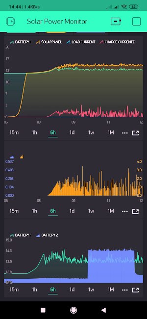 | 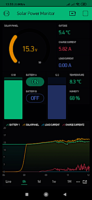 |
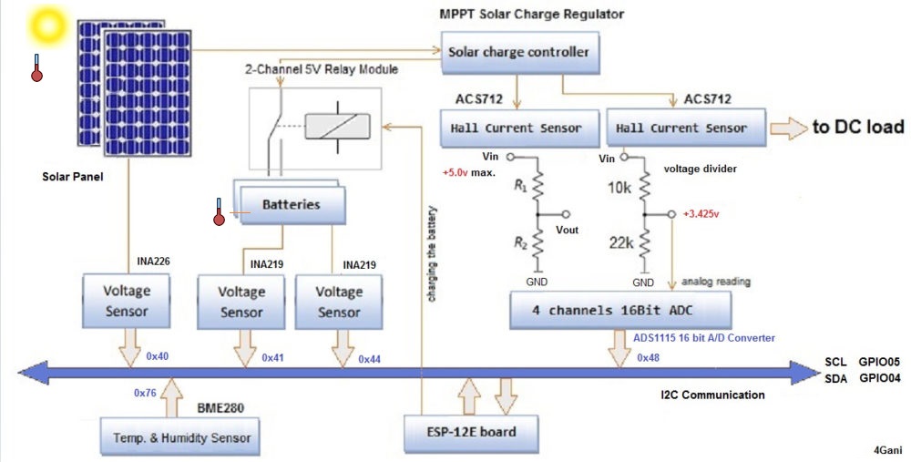
Complete circuit diagram for Solar Monitoring is given below:
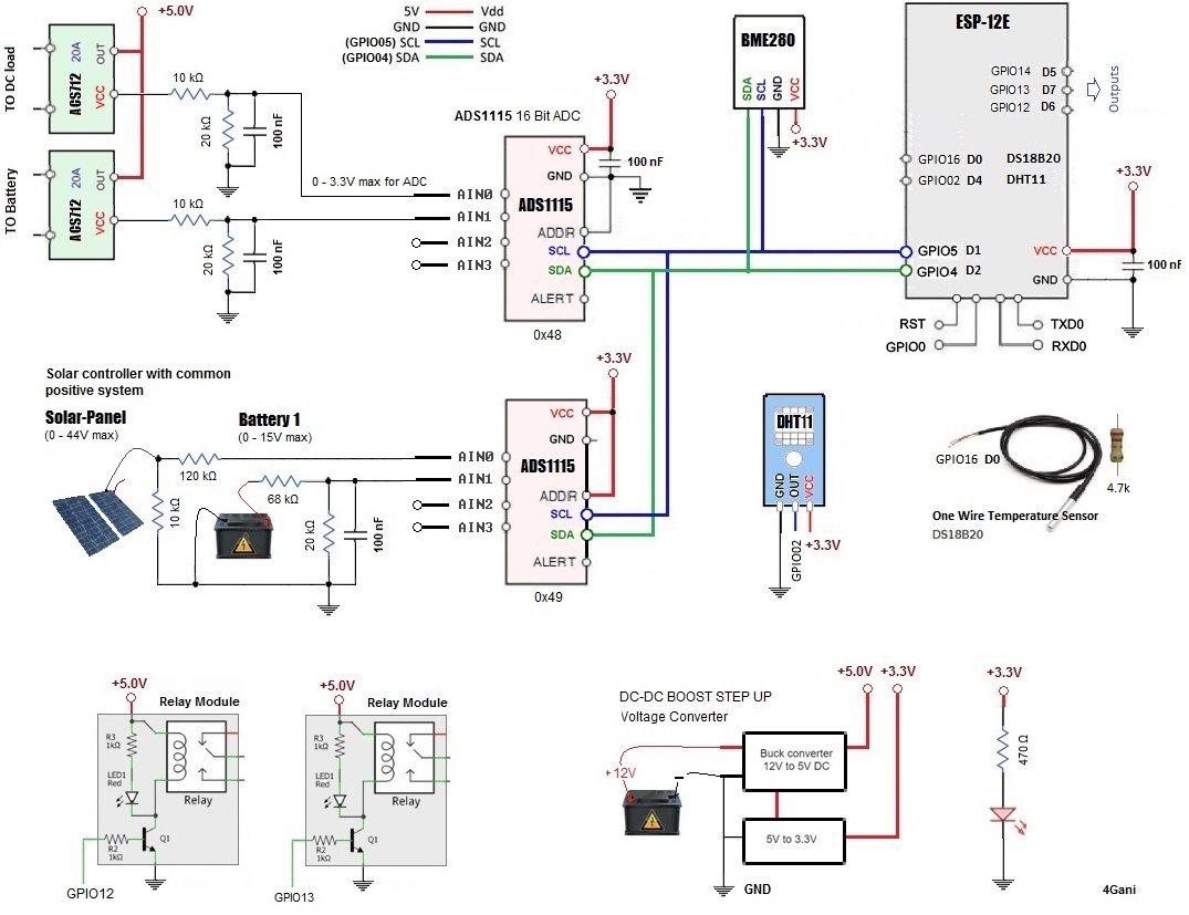 |   |
Continue …
Installing the ESP8266 Arduino Addon
To begin, we’ll need to update the board manager in Arduino,
A- Go to the File > Preferences and add the URL
“http://arduino.esp8266.com/stable/package_esp8266com_index.json” into the “Additional Board Manager”
B- Navigate to the Board Manager by going to Tools > Boards > Boards Manager. and look for esp8266 then select Install.
NodeMCU 1.0 (ESP-12E Module)
Code checked in to the GitHub repository under https://github.com/forgani/Solar-Monitoring-System
Interested in learning more about this project.
My company is a System Integrator and I need to monitor Solar Panel Kit already installed in remote-areas. We need to monitor the performance of each kit:
1. Voltage generated for the whole solar-panel kit.
2. Conditions of the battery (is it full loaded, what is the level of voltage,
etc,. etc).
3. Amounts of Kwatts consumed by all the load (homes appliances).
4. Report errors of alarms for the overall-system.
Also, the data capture needs to be transmitted via a LoRaWAN network into a LoRa Gateway.
Hope to hear from you
Regards
Alvaro Ramirez
Director
Hello, I wanted to know how much does this system consume on a daily basis in Wh? Thanks.