
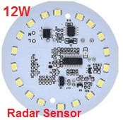
LED Light with Motion Sensor
LED Ceiling Lamp with Microwave Radar Sensor Module AC 220V
 Product model: YX-3012
Work voltage: AC 180V-240V
The sensor works very well, but unfortunately we cannot change the delay time of the light.
Don’t worry, we can modify the sensor simply by adding an additional potentiometer to the board.
You can adjust delay time for the sensor to switch the light off once it does not detect motion.
Now let’s take a quick look at the functionality of this Module.
This device consisted of 4 parts.
- A proximity sensor, It is using microwaves and a Doppler effect to detect the presence of humans.
- EG0001/TM2291 chip detector (similar to BISS0001 signal processing integrated circuit), which doesn’t have the sensitivity trim pots.
- Power supply to regulate the power required for LEDs and +5 volt system DC
- LED Driving Circuit Based on BP2832A
Components of a LED driver circuit are:
- LED Driver Circuit BP2832A
- MB6F/MB10F Bridge rectifier and an amplifier stage for taking the signal from the detector.
The output signal Vo from detector is amplified by the transistor U1 and drives the BP2832A.
The proximity sensor on board uses Doppler Radar. It’s not exactly the same as RCWL-0516 but the pin out of ICs are the same. EG0001 or TM2291 are almost identical to the BIS0001.
For decrease/increase the delay time of the sensor?
The EG0001 IC on board processes in non-retriggerable mode.
No matter how much movement is in the front of the sensor, it will stay high for the period of time given by Tx and after that it will go off for the period time given by Ti.
After that if any movement is detected again by the sensor, it will go on again, and so forth.
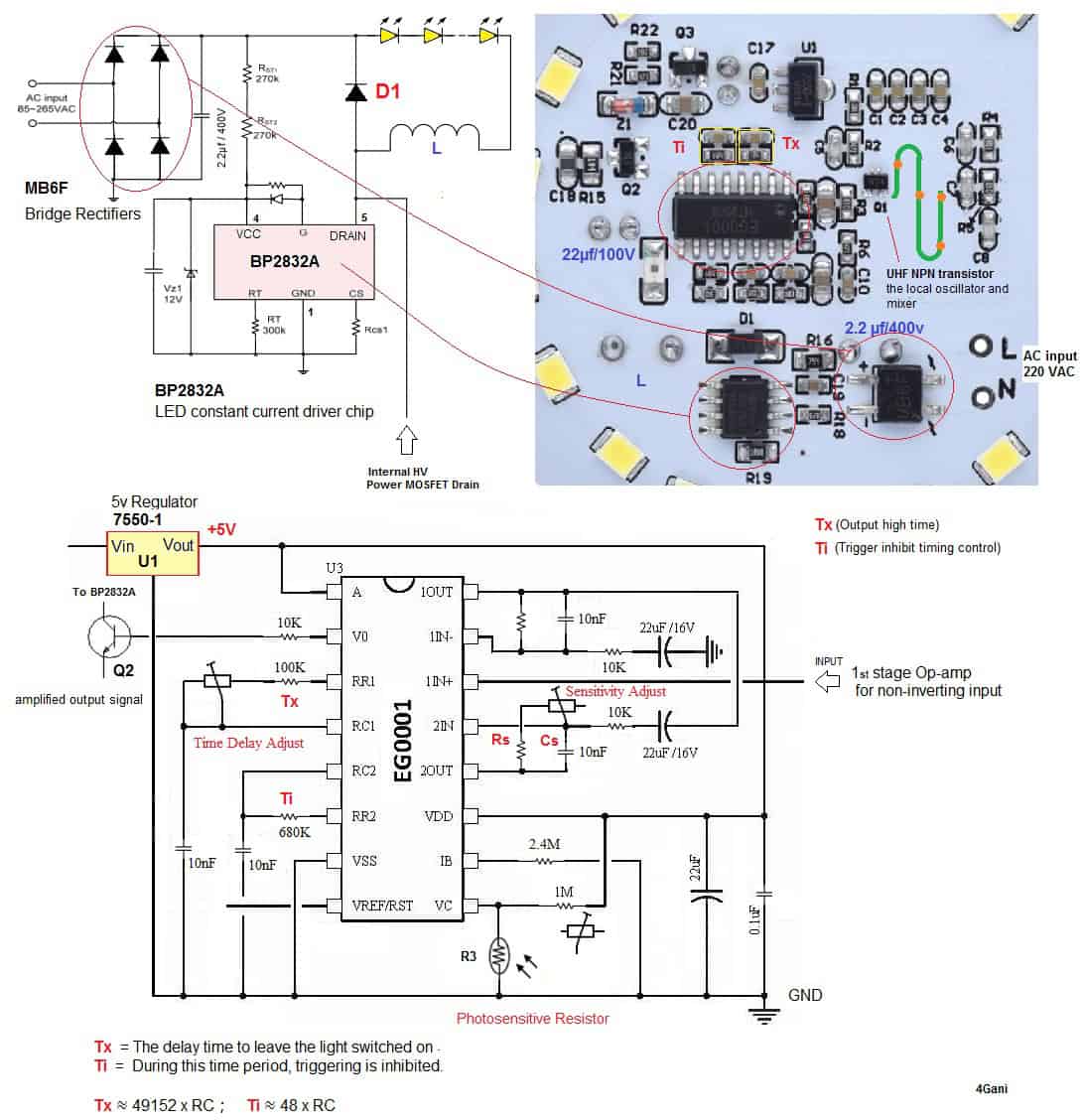
Tx = The time duration which the output pin (V0 of BP2832A) remains high after triggering. 49152*RC
Ti = During this time period, triggering is inhibited. 48*RC (is not needed to be changed for normal home usage)
According to the datsheet
By default, the Tx delay time is about 49 seconds (49152 x 100kΩ x 10nF) and the Ti trigger blocking time is about 326 millisecond (48 x 680kΩ x 10nF).
We can handle it by placing a 1MΩ trim pot in series with the 100k fixed resistor on board. See the diagram and circuit above. I marked the RC on it.
I wanted to reduce the time form 49 to 25 seconds, so I solder a 100kΩ resistor in parallel with the existing 100kΩ smd resistor on board.
R3 is a LDR (Light Dependent Resistor). It’s used to detect environmental illumination.
It has a resistance which increases in darkens and decreases with light.
If the environment has become more bright, R3 resistor value will be reduced, so that the input of pin 9 is kept at a low level, thereby blocking Trigger signal.
For reducing the sensitivity of the sensor?
To adjust the values of Rs to reduce the gain Vref (which sets several of the voltage references inside the chip) and make the device less sensitive.
You can handle it by placing a trim pot in series with a fixed resistor Rs.
This is marked as Rs/Cs on the schematic above. The series resistance would be between 470kΩ and 1MΩ.
If the resistance value is about 680KΩ, then the sensor sensitivity for detection is a few meters.


Leave a Reply