
Monitor flow & return temperatures of boiler
Measurement of flow and return temperatures of a heating system
with a SONOFF device and Home Assistant.
I used Sonoff because they are all in one with a power supply and a box.
But before we use them, we should know some important details about them.
The device will not boot into its regular operating mode if GPIO02 is pulled low at boot, and so GPIO02 is useless.
Below you will find a table of all usable GPIO pins of the Sonoff Basic and a configuration file that exposes all of the basic functions.
(Started on 20 Dec. 2022)
Sonoff Basic R2 V1.0
| GPIOx | Label | INPUT/OUTPUT |
| GPIO00 | Button (inverted) | turn buzzer off |
| GPIO01 | TX pin (C1 Pin 2) | |
| GPIO03 | RX pin (C1 Pin 3) | High at BOOT It’s suitable for 3xDS18B20 |
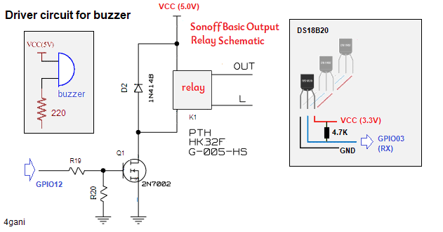
| GPIO12 | Relay | OK (PMW is suitable for Buzzer.) |
| GPIO02 | Free | Boot fails if pulled down. |
| GPIO13 | Green LED (inverted) | OK |
| GPIO14 | OK Water binary Sensor |
I’m using GPIO03 (Rx) for DS18B20 temperature sensors, which does not have any boot function restrictions.
GPIO14 is definitely not connected as a default (Sonoff Basic R2 V1.0), so I soldered a wire directly to the chip in order to access GPIO14.
Connect Sonoff device for the ESPHome install
Complete ESPHome Installation Guide: 4 different ways to install ESPHome
Connect the USB FTDI programmer to the computer, and hold down the basic board button to connect GPIO0 to GND while the device is booting to put it in programming and flash mode.
Note: We supply USB power to Sonoff via FTDI, and make sure you set the 3.3V setting on FTDI; 5V will cause damage.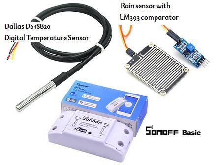
- 3x DS18B20 temperature Sensor
- moisture sensor (3.3V-5V) binary leakage sensor
- 1x 4.7k Ohms Resistor
- a SONOFF device
The rain sensor board module uses a voltage comparator LM393, and the result is given as output in two formats, digital (0 and 1) and analog AO.
Using With Sonoff Basic—ESPHome
- Open the ESPHome interface and click on the New Device button.
- Enter device name of your choice as well as your WiFi name and password.
- In the next dialog, click on the “Pick specific board” radio button and select the Generic ESP8266 (for example, Sonoff); then click the “Next” button.
- Click the install button, and you will have ESPHome installed on your ESP device.
When the ESP installation is finished, the Sonoff device will be automatically added to the ESPHome Dashboard.
Remove the Sonoff BASIC cover and desolder the relay and add a buzzer with a 220-ohm resistor instead.
The DS18B20 are “one-wire” bus sensors. So we are connecting all of the DS18B20s in parallel, sharing all of the VDD, GND, and signal pins.
Next, we connect signal pins to digital pin GPIO03 (RX) on the Sonoff.
Temperature sensors are wired according to the following scheme.
The 4.7 kOhm resistor should be soldered between the DS1820 signal pin and VCC.
Getting Sensor IDs
In order to get the address of each DS sensor, simply start the firmware on your device with a configured Dallas hub and observe the log output (the log level must be set to at least debug!).
Note that you don’t need to define the individual Dallas sensors just yet, as the scanning will happen even with no sensors connected.
For example, with this configuration:
Device name: sonoff_1
Device type: Generic 8266

wifi: ssid: !secret wifi_ssid
password: !secret wifi_password
# Example configuration entry
dallas:
  - pin: GPIO03

# Note: You don't have to add any sensors at this point
Now we can add the individual sensors to our configuration: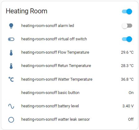
Some specifics about the code above
- The water sensor exposes the entity binary_sensor. That becomes on if a water leak is detected by the sensor’s probe.
- The automation trigger is based on the changing state (on / off) of this entity.
- The notification message will be sent to your smartphone via the alarm stream to be sure the vibrate/silent ringer mode won’t prevent your device from ringing.
The code is checked into GitHub at: forgani/Temperatures-of-a-heating-system
⮜ Configuration of Home Assistent
3 phase energy monitoring with ESPHome ⮞
Leave a Reply