
Home Energy Monitor with ESP-12E & CT (Blynk App)
Building a Home Energy Monitor with ESP-12E & CT Sensors
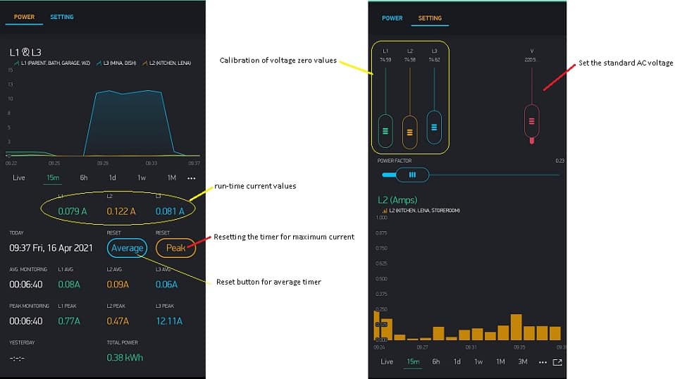
Visualize the data by using the Blynk app
A system to control the energy usage and monitoring the current of the 3-Phase AC load of your home in real time.
This system helps you to remotely monitor the used energy for each of the three-phases.
You can also monitor the three-phase line for unbalanced voltage consumption and also ideally equally distribute the load with the consumption over the 3 phases.
The most important components are obviously the ESP-12E microcontroller, 74HC4051 Multiplexer and the 3 x CT sensor (Current Transformer).
![]()
I’m using the AC current transformer to measure the AC current indirectly and finally, monitor the data by using Blynk app.
Code checked in to the GitHub repository under https://github.com/forgani/3_phase_energy_monitor
Components:
- ESP-12E microcontroller + 74HC4051 Multiplexer
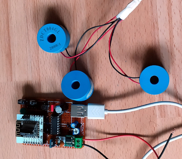
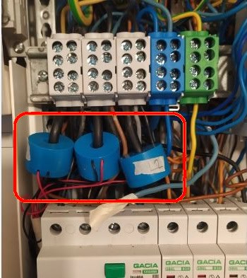
- 3 x CT Sensors AC current transformer which has an AC output. (You can use any standard current transformer)
(This sensors clamp over the main cable) - Blynk Server & Blynk app builder
(This tool allows you to make apps for your projects by using various widgets. )
Software Used:
- Arduino IDE
- Blynk Mobile App (for Android or iOS)
- Libraries: EmonLib, BlynkSimpleEsp32, NTPClient, Time
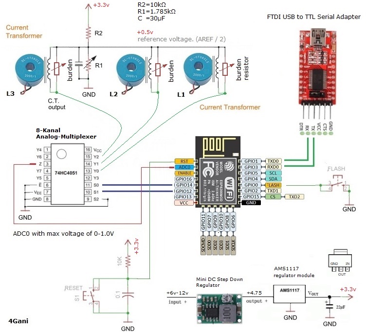
So as we know the ESP-12E has only one single analog input, with an input range of 0 – 1.0V.
The ESP-12E ADC (analog to digital converter) has a resolution of 10 bits and the analog input measures varying voltage levels between 0V to 1.0V.
The measured voltage will assigned to a value between 0 and 1023bits, in which 0V corresponds to 0, and 1.0V corresponds to 1023 bits.
To measure the 3 phases we need 3 ADC input.
So I’m increasing the number of analog inputs to three by using a 74HC4051 multiplexer.
With the 74HC4051 we can connect up to 8 analog devices to the single analog pin on the ESP-12E (It uses 3 digital pins for addressing, from which two of them will cover my purpose).
The AC current transformer which I’m using has 2000 windings and can measure up to 28 Amps.
We are supposed to adjust the output of the CT in connection with a burden resistor so that the AC output voltage is exactly 1V sine wave.
The formulas Here and the Tool for calculating burden resistor size helped me in my case.
So for example for a CT with 2000 windings and a burden resistor of 25Ω I measured a max primary current of about 28A. (35Ω for 20Amps).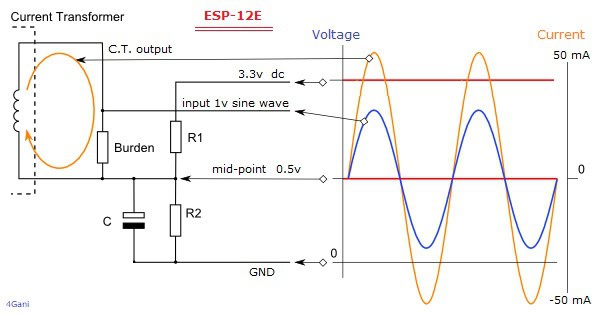
Burden Resistor (ohms) = (AREF * CT TURNS) / (2√2 * max primary current)It should be calculated for ESP-12E so that the maximum of the CT output AC voltage is exactly 1V.
Burden resistor for maximum primary current of about 28Amps is 25Ω and for 20A is 35.35Ω.
For Burden resistor I used a 100Ω potentiometer and trimming the resistance into 25Ω.
For voltage divider I used a 10kΩ resistor with a 2kΩ potentiometer and trimmed the resistance so that the voltage divider took the 3.3V down to 0.5V as a middle point for the 1V ADC range.
Vin = 3.3v
Vout = 0.5v
Voltage Divider Resistor:
R2 = 10kΩ, R1 = 1.785kΩ
Capacitor = 30µF
The 74HC4051 is an analog multiplexer. This device is a single 8-channel multiplexer. It has three binary control inputs (S0, S1, and S2) which can be controlled by 3 GPIO pins; 14, 12 and 13.
The three binary signals select 1 of 8 channels and connect it to the output (Z).
S0 – Arduino GPIO14
S1 – Arduino GPIO12
S2 – Ground
You are welcome to download or review the program code (Home Energy Monitor) from here.
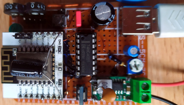
The video shows my module and their components.
A short video to show the ESP board
To visualize the data, I created a simple Blynk app by using blynk mobile visual interface.
|
|
–
Calculating daily energy consumption gets a bit complex.
The two steps to calculating the energy are:
- measure the power over dt time.
- At the end of the day, all measured amounts of powers(dt) are added together and the energy costs are calculated from this summation.
Power measured as changing the voltage and current during a time period dt:
P(dt)=U*I(dt)
then the energy dissipated during the time interval [0,t] is given by the integral or the sum of the measured values:
E=U*∑I(dt)
Here is a suggested source code for calculating of daily consumption power in kWh.
It should be running around every second.
// execute around one second
float costFactor = "26.9"; // Cent/kWh  Grundpreis. 9,90 Euro per Month
float loadVoltage= "230";  // Volt
float SumPowerL1=0, SumPowerL2=0 , SumPowerL3=0;
void clockDisplay() {
  float currentMillis = millis();
  float currentSec = second();
  float dt;
  if (currentSec > lastMeasurementSec) {
    dt = (currentSec - lastMeasurementSec) + (currentMillis-lastMeasurementMilli)/1000;
  } else {
    dt = (currentMillis-lastMeasurementMilli)/1000;
  }
  SumPowerL1 += currentL1 * dt;
  SumPowerL2 += currentL2 * dt;
  SumPowerL3 += currentL3 * dt;
  if (hour() == 23 && minute() == 59 && currentSec >= 57 && daily == false){
    float dailyEnergy = ( (SumPowerL1 + SumPowerL2 + SumPowerL3) * loadVoltage ) / (3600*1000); //kWh
    if (dailyEnergy > 0) {
      float energyCostDaily = dailyEnergy * costFactor;
      Blynk.virtualWrite(vPIN_DAILY_ENERGY_USED, dailyEnergy);
      Blynk.virtualWrite(vPIN_DAILY_ENERGY_COST, energyCostDaily);
    }
    daily = true;
    SumPowerL1 = 0;
    SumPowerL2 = 0;
    SumPowerL3 = 0;
  } else if (hour() == 0 && minute() < 1){
    daily = false;
  }
}
Leave a Reply